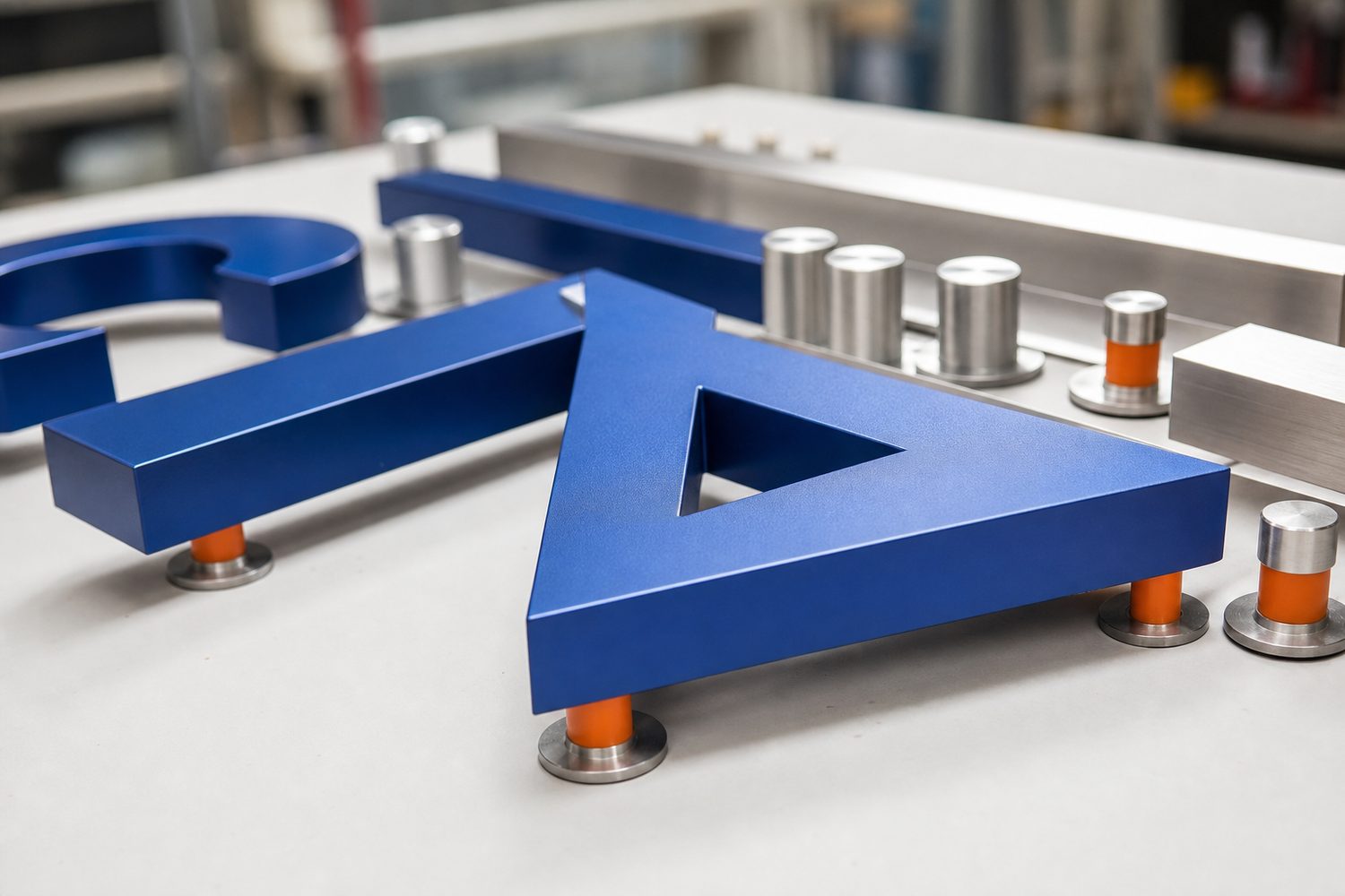
Document the receiving condition
Name the actual substrate: cast concrete, masonry veneer, structural masonry, wood framing, metal studs, curtain wall, siding, roof structure or a purpose-built foundation. A finish surface is not necessarily a structural substrate. Use drawings, scans, probes or selective investigation as appropriate rather than assuming what lies behind a wall.
Map loads and responsibility
Weight is only one load. Wind, snow accumulation, eccentricity, vibration, thermal movement, maintenance activity and accidental impact may matter. Establish who designs the attachment, who verifies the structure, who supplies calculations or stamped documents when required, and who reviews substitutions. These responsibilities should appear in contracts and submittal requirements.
Coordinate penetrations
Every penetration through roofing, flashing, weather barriers, insulation or finished assemblies needs a compatible detail. Determine who opens, flashes, seals and warranties the work. Avoid trapping water behind raceways or mounting plates. Confirm standoff depth, drainage and access for sealant replacement where sealant is part of the joint.
Choose hardware as a system
Specify material, grade where relevant, diameter, embedment, edge distance, spacing, washers, isolation and finish. Generic notes such as “provide suitable anchors” leave critical choices until installation. Adhesive anchors and specialty fasteners have substrate, hole-cleaning, temperature and inspection requirements. Follow manufacturer data and qualified design.
Make templates accountable
Full-size drilling patterns and mounting templates should identify orientation, datum, message or component ID, hole size, hidden conflicts and revision. Check them against fabricated parts before site use. A mirrored, stretched or outdated template can turn a correct design into a damaged façade.
Plan installation access
Ask how components reach the location, how lifts or scaffolds are staged, whether public circulation closes, where electrical disconnects sit and how future service occurs. Large panels may require seams simply because access routes are limited. Verify door, elevator, corridor and turning dimensions when interior components arrive assembled.
Inspect before covering
Where anchors, wiring or blocking become concealed, define hold points for photographs and inspection. Record installed conditions, deviations and approved changes. Do not let a field improvisation disappear behind a panel without review by the responsible party.
Close out for the next person
Provide as-built locations, fastener information, structural documents, electrical diagrams, access instructions, spare components and safe removal sequence. The future facility team should not have to reverse-engineer the installation to replace one damaged letter.
Safety and code limit
Mounting can create life-safety risk. This educational note is not structural engineering, envelope consulting, electrical design, fall-protection planning or installation instruction. Site-specific work belongs to qualified professionals and applicable authorities.